Calibration Steps
After the initial installation of the Fotodijit software, the calibration process must be performed. This process is required to ensure accurate digitizing.
![]() After calibration is completed, the position of the camera and the table must not be changed.
After calibration is completed, the position of the camera and the table must not be changed.
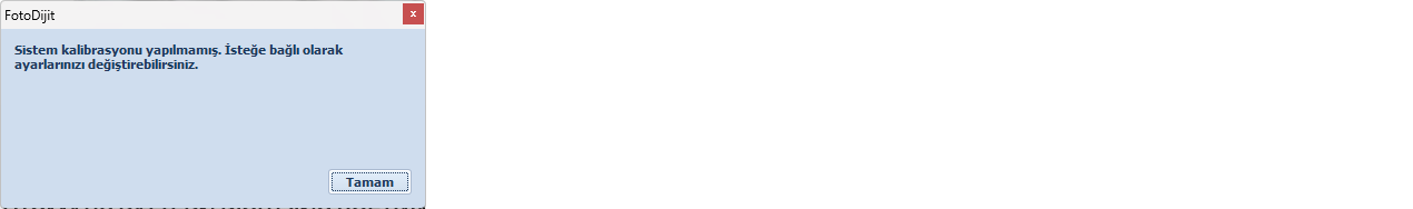
Launch the Fotodijit software and proceed by clicking OK in the welcome screen.
After clicking OK, the Options window opens automatically. Switch to the Camera tab.
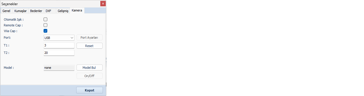
In the opened window:
- Enable the WiaCap option
- Select USB as the port
- Use Find Model to select your camera model (the camera must be powered on and connected to the computer)

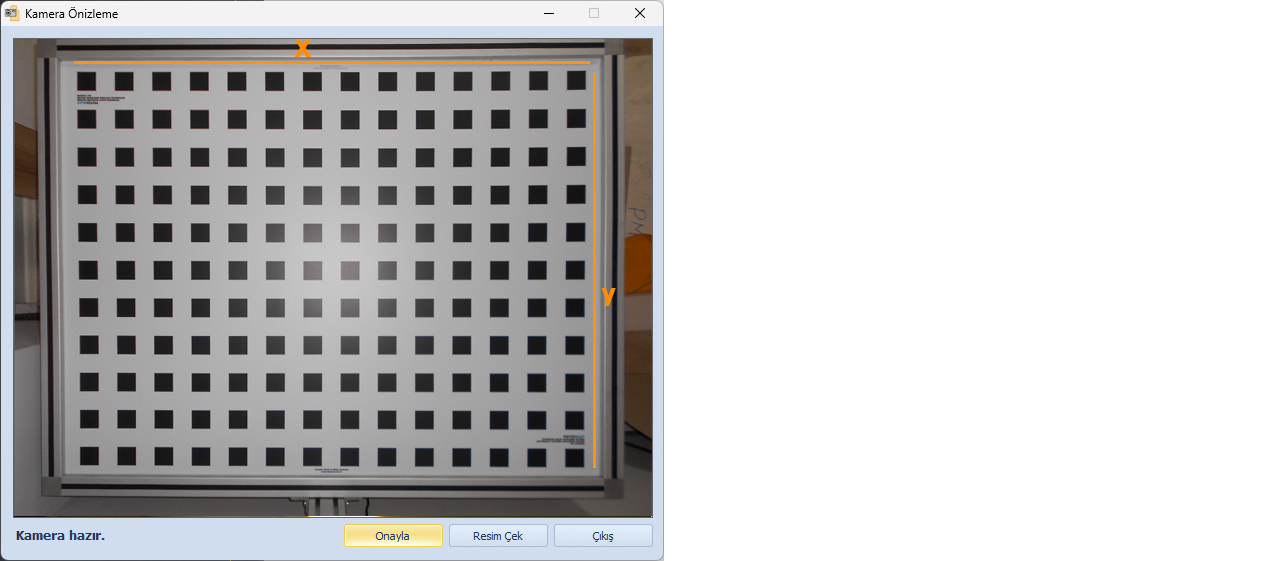
Click OK to confirm and close the Options window. Then, the Camera Preview screen will open automatically.
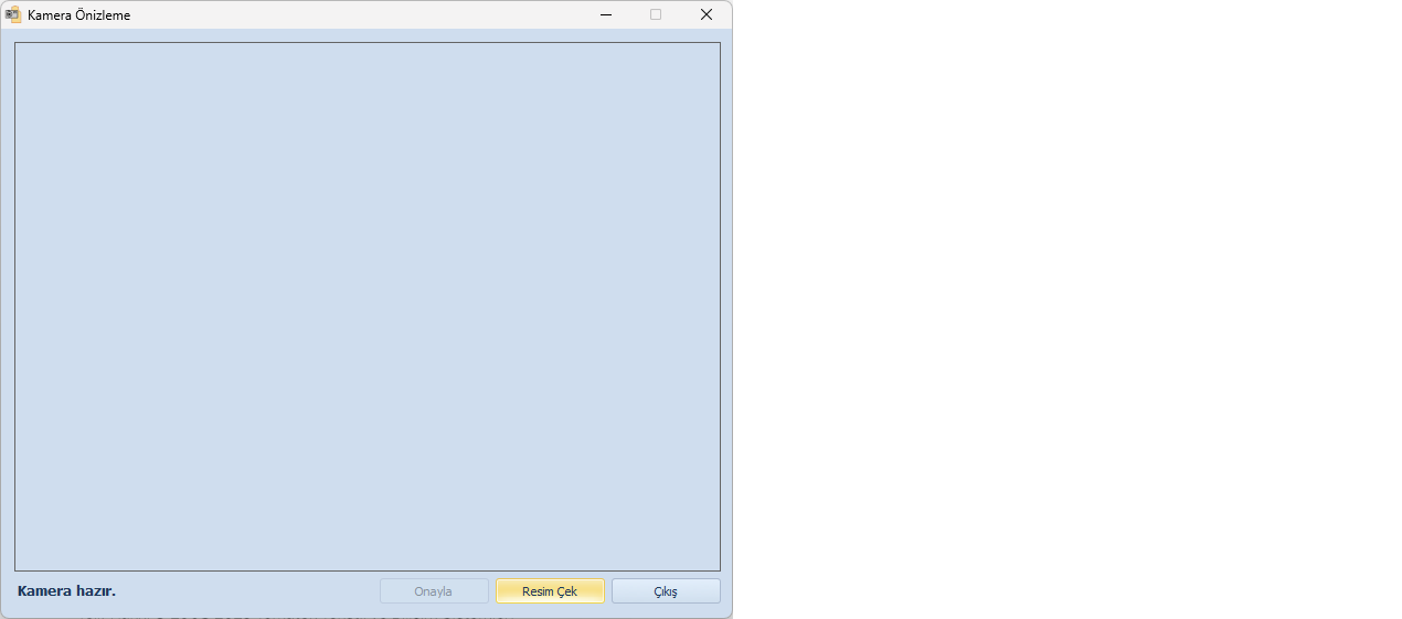
In the Camera Preview screen, click Capture Image to take a photo of the calibration board.
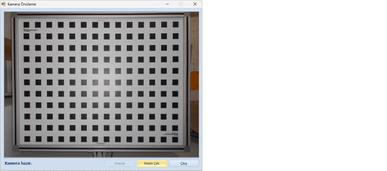
Adjust the camera position using the mount. Repeat the capture process until the calibration squares in the image are as parallel as possible to the X and Y axes.
Once a proper image is obtained, click Confirm to load it into Fotodijit.
Requirements for Proper Calibration
- The camera should be positioned to capture the entire table
(it is not necessary to see all aluminum edges) - Calibration squares must be parallel to the X and Y axes
- Lighting conditions should be sufficient to obtain a clear image
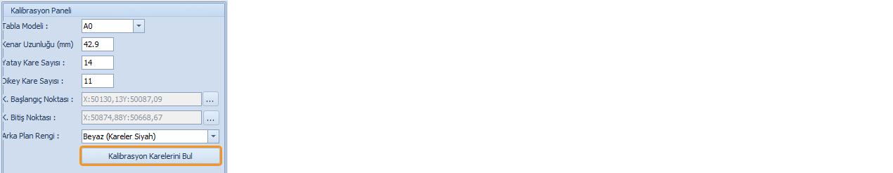
Starting the Calibration Process
From the Table Model section, select:
- A0 (125 × 97 cm) or
- A0+ (155 × 117 cm)
If a different table is used, select Custom and manually enter the number of horizontal and vertical squares.
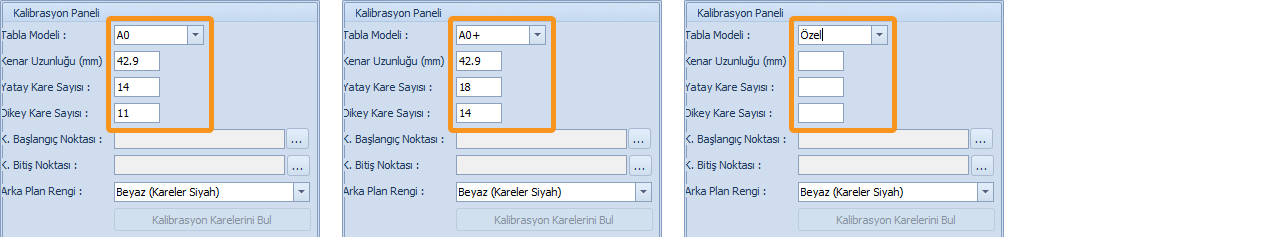
For A0 and A0+, the number of squares and the size of small squares (42.9 mm) are filled automatically.
For the Custom option, you must also enter the size of the small squares.
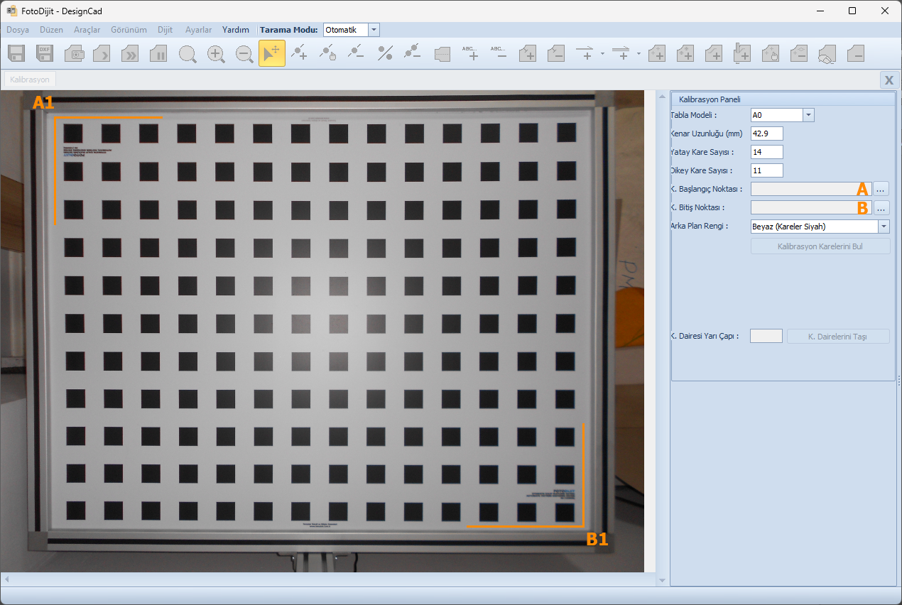
Selecting the Calibration Area
1.) Click the three-dot button next to Start Corner Point (A) and select the top-left corner (A1) on the calibration image.
2.) Click the three-dot button next to End Corner Point (B) and select the bottom-right corner (B1), forming a rectangular area.
After selecting point B1, the calibration area will appear as a red boundary.
The outer rows of squares must remain inside this boundary.
If the selection is incorrect, it can be redefined.
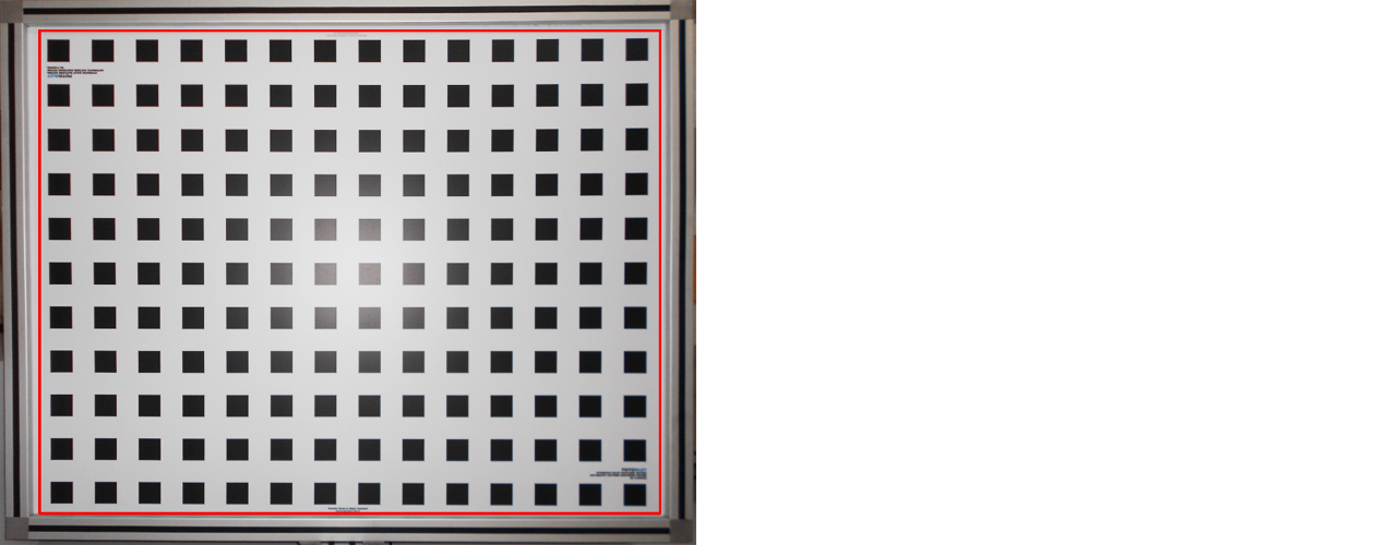
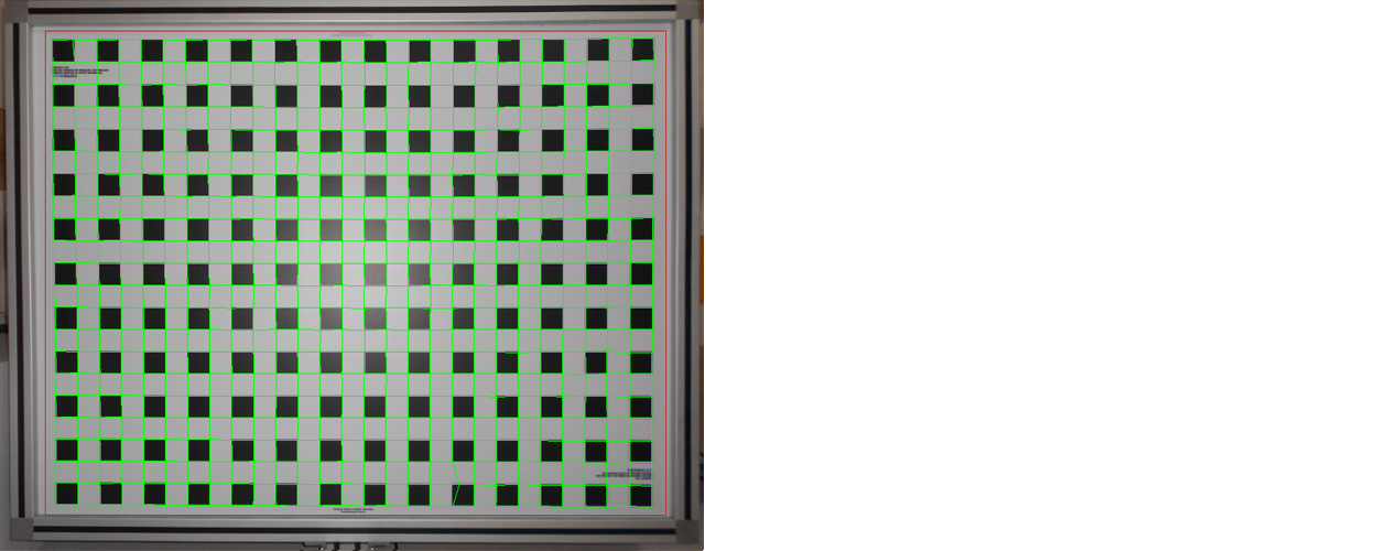
After selecting the boundary, click Detect Calibration Squares.
Depending on image quality, scanning may take approximately 10–15 minutes, after which all square positions are detected.
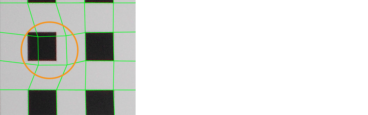
If some green squares are not properly aligned due to lighting or other factors:
- Use the Move Squares
 function to align them with the black squares.
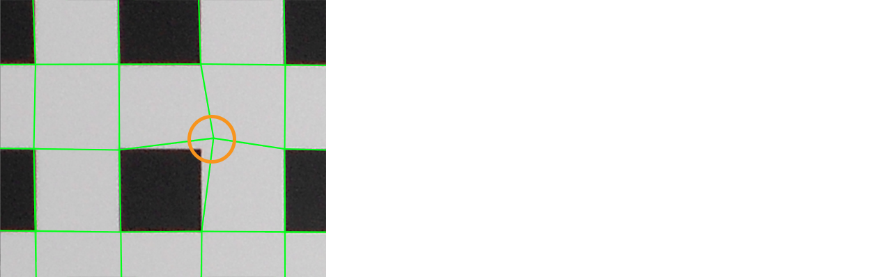
- Use the Edit Lines
 function to manually adjust lines from corner points
 |
|
After completing all adjustments, click Finish  and confirm with Yes.
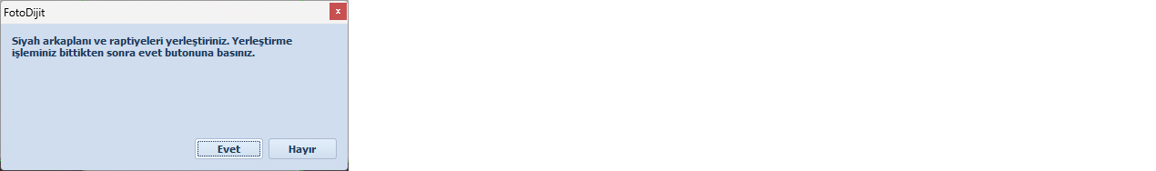
Place the black background cloth on the table and click Yes to continue.
The capture screen will open automatically. Click Capture Image, then confirm the image.
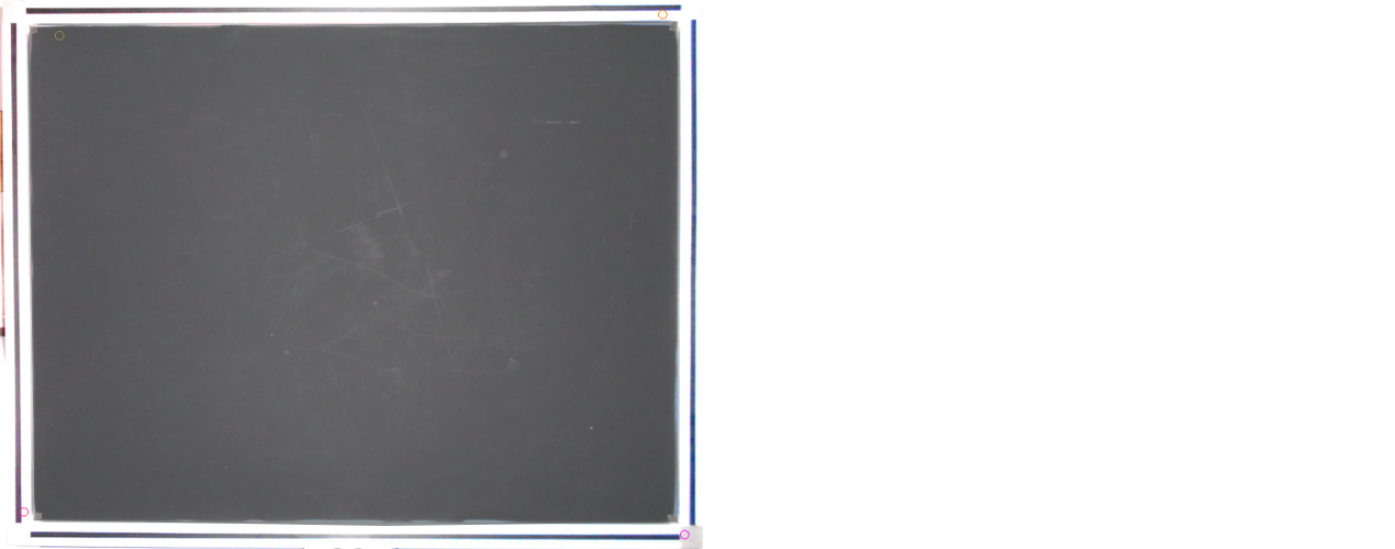
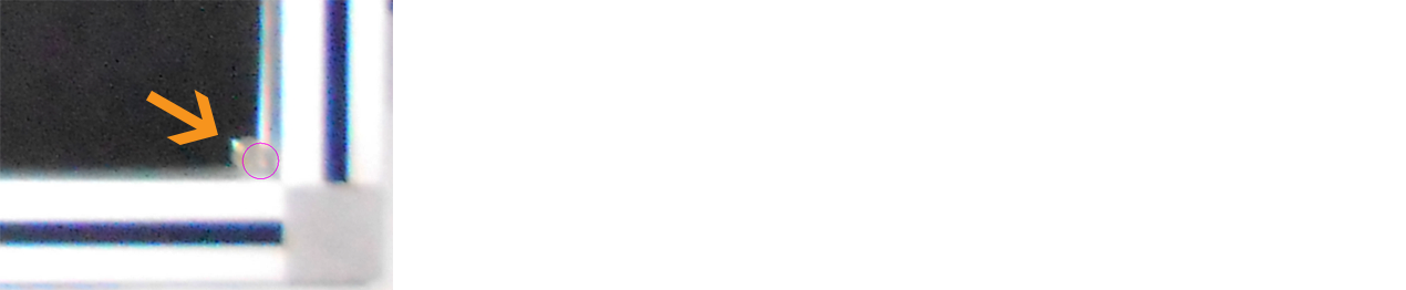
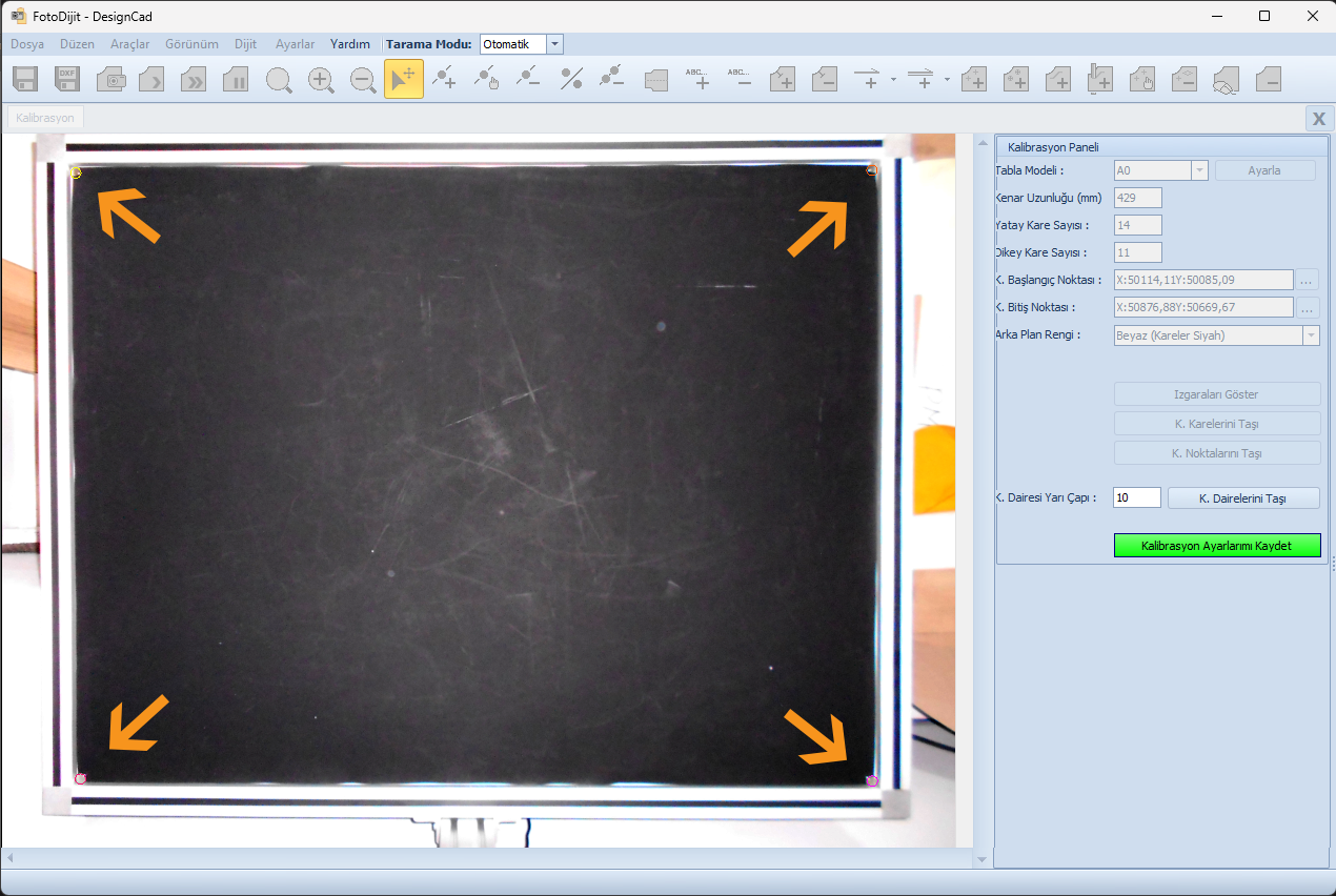
Enter 10 in the Control Circle Radius field (value in mm for control circles) and click Move Control Circles.

Move the four control points to the corners of the table. (These points will be used to verify camera alignment in future captures.)
After positioning all four circles, click Save Calibration Settings to complete the process.
Confirm the message “Calibration settings saved successfully” by clicking OK.
Settings in this tab require advanced technical knowledge. For safe and proper use, please contact Tematek Textile and Information Systems for technical support. |
To download the Fotodijit Calibration Steps document as a PDF, please click here.